Getting Started with ElumTools®
|
ElumTools is an incredibly intuitive software Add-In for Autodesk® Revit® to assist designers in quantifying and understanding light. Using ElumTools, you can predict various lighting metrics (illuminance, luminance and more) on any surface or imaginary plane due to electric lighting fixtures (luminaires). The electric luminaire instances can already be present in your Revit model, or quantity and position can be produced by ElumTools (see the Layout Assistant). Daylight analysis can include electric luminaires or consider the effect of natural light only. |
|
The calculated results can be viewed within the framework of Revit views, summarized in Revit schedules and reviewed in an interactive visualization that is a byproduct of the calculation process. Using ElumTools avoids the need to utilize third-party lighting software outside of the Revit environment.
What is required for an accurate lighting computation?
The entire concept of ElumTools is based on the ability to leverage content within your Revit model as building blocks toward the composition of an accurate lighting computation. The execution of an accurate calculation of any lighting metric, illuminance for example, on a surface or work plane requires that the following quantities be defined:
- Spatial geometry as contained in Rooms, Spaces, Areas, Regions or even specific Views which are used as calculation volumes.
- Surface reflectances mapped by material or category. All geometry must have a material assigned to be visible in an ElumTools calculation.
- Luminaire families with photometric source type and valid IES file.
- Luminaires positioned in the Revit model (can also be produced by ElumTools).
- For Daylight calculations visible transmittance must be assigned in the Materials Mapping dialog, project location and orientation is obtained from the Revit project file and can be modified in ElumTools Daylight dialog.
With these items known, you can perform a calculation based on proven Radiosity technology to provide the luminous exitance for every surface included in the selected geometry. Based on the calculated luminous exitance, ElumTools can derive the illuminance (or luminance) at any point on that surface. Additional computations can yield illuminance on imaginary surfaces such as work planes, Unified Glare Rating (UGR), Daylight Factor (DF) and Photosynthetic Photon Flux Density (PPFD).
What already exists in Revit?
| BIM models created in Revit contain an enormously complex three-dimensional, parametrically related system of building components. While ElumTools allows lighting calculations for an entire model, this is generally not an efficient way to approach lighting design. Fortunately, there are easier methods that allow you to perform the calculations for individual building areas or groups independently. This simplifies the calculations to the point where the lighting design of the area of concern can be iterated and finalized according to your specific requirements. |
|
Spatial geometry
|
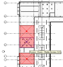
Revit provides an intuitive separation of interior building areas using entities known as "Rooms" and "Spaces." Rooms are defined in Revit Architecture, while both Rooms and Spaces are defined and available in Revit MEP. ElumTools allows you to select Rooms or Spaces individually or in groups to define the spatial geometry for the lighting computation. Exterior environment geometry can be captured using Revit Regions and Areas.
ElumTools also allows the selection of random Revit entities to define your own environment for lighting calculations.
ElumTools will work with linked models; see our Guidelines. |
|
Surface reflectances & transmittances
|
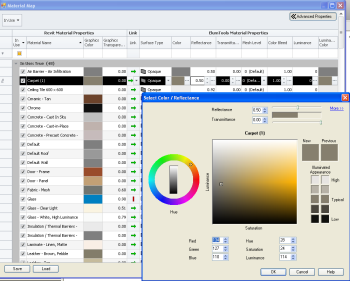
The reflectance and color of various geometric surfaces are important for accurate calculation of reflected light and visualization. ElumTools obtains this information through "Material Mapping".
All Revit materials are assigned a "Graphics Color" that may or may not represent the intended surface color. ElumTools can calculate the surface reflectance from the RGB components of the material graphics color. However, this may not be the reflectance you intended. ElumTools allows all Revit materials to be "mapped" to ElumTools materials in terms of surface color and reflectance, as well as surface type such as translucent or transparent. This material mapping process is done on a project basis, with all Revit materials presented for mapping in the Materials Mapping dialog. Once the map is created, your lighting calculations can be completed across all boundary types used in the project without revisiting this area.
|
|
Reflectances can also be set by Revit Category such as all ceilings or walls. This is also performed in the Material Mapping dialog by using the switch to "View Category Overrides". Any surfaces not covered by a category override will continue to use the reflectance as set by material. This is often the best default mode of operation and simplifies the process substantially.
The material mapping process is also a critical part of daylight analysis as all glazing must be assigned the correct visible transmittance. ElumTools will automatically locate all materials with name containing the words "glass" or "glazing" and assign a Transparent surface type. Exceptions: "fiber glass", "glass fiber" and "fiberglass". You must locate those materials in the ElumTools material mapping dialog and assign the correct visible transmittance, or, utilize the category override for Daylight Transition glass.
Luminaire photometry and associated factors
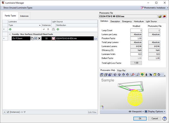
The ElumTools Luminaire Manager catalogs all lighting fixture families you have defined in the Revit project. Lighting fixture families may be provided by luminaire manufacturers or created by you.
All luminaire families must contain a light source definition with a "Photometric Web" source type to be used for accurate lighting calculations. ElumTools will ignore light source definitions classified as "Spot," "Spherical" or "Hemispherical." Families containing light source definitions other than "Photometric Web" can be revised using the Revit Family Editor. Once revised, the ElumTools Luminaire Manager provides an interface for you to select a photometric data file to be assigned to a family with a Photometric Web source. Photometric data files must be in IES LM-63 standard format and can reside anywhere accessible to Revit. ElumTools accepts IES files in Type C photometric coordinates only.
Luminaire position and aiming
|
Luminaire positions existing in your Revit model are available to ElumTools. Their properties need only be finalized in ElumTools' Luminaire Manager prior to calculation.
ElumTools assumes the luminaire family is built correctly with a "Photometric Web" light source setting and with the source position properly located and aimed. Incorrectly built luminaire families can usually be corrected in the Revit family editor.
ElumTools provides the ability to change the size of the luminaire luminous area, edit color temperature (or assign a filter) and enter any required factors such as light loss or photosynthetic photon flux (PPF for Horticulture).
|
|
What else is needed?
ElumTools provides additional capabilities necessary for effective use as a design medium for electric lighting.
Point-by-point
|
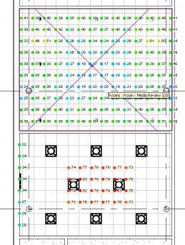
Calculation Points satisfy the need to report point-by-point lighting calculations (illuminance for example) across a grid of potential light meter locations. ElumTools provides the ability to easily place calculation points within Rooms, Spaces, Regions and Areas using the Add Points command . Points can be added to multiple boundaries at one time (multiple Rooms for example) and unwanted points masked from the calculations.
Additionally, for vertical surfaces such as walls, or planar surfaces like table tops, you can attach calculation points to those surfaces using the Add Points - Planar Face version of the same command. Virtual planes such as a vertical plane of points in the middle of a room can be specified using an offset distance referenced to an existing surface.
Calculated results can be made visible in Revit views, (2D or 3D), and are sorted intelligently by view (only those points on the current view level are shown) using the View/Update Results command.
All statistics are tabulated and available for Revit schedules. |
|
Visualization
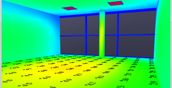
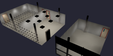
| ElumTools provides a fully interactive and photometrically correct visualization of the calculated geometry in a pop-up window as a byproduct of the calculation. You can examine this rendered environment interactively, or from any viewpoint either inside or outside the space. A post radiosity process ray trace can also be applied to any viewpoint to visualize specular reflections and glossiness. Additional visual aids are provided, including scaled pseudocolor imagery, point-by-point overlay, isolines, spatial maps and the ability to visualize and quantify direct and indirect light components separately. ElumTools visualizations are "sticky" to retain your view and calculation point settings for repeated viewing using the Rendering Manager. |
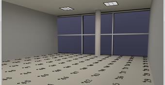
|