
Add Calculation Points_Line
|
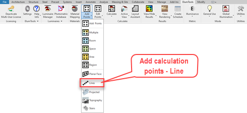
ElumTools will allow you to attach calculation points to Revit Property Lines, Model Lines, Detail Lines and even perimeter boundaries of Regions and Areas.
You can add calculation points to any of the above by selecting the Add Points command with the Line option, followed by a click on the line in Revit. This sequence can also be performed in reverse by selecting a line (or multiple) in Revit followed by the main Add Points button on the ElumTools toolbar. This bypasses the need to access the specific command from the menu. |
|
Calculation point dialog - Line
Once the Line(s) have been selected, the Add Calculation Points dialog will appear for you to assign specific details to the calculation points. Inputs are slightly different from area-based grids. Point spacing is your only concern. Workplane height does not apply to line-based points. Similar to other calculation points functions, by default, the illuminance Metric is selected and all Modes are active (General Use, Emergency, Daylight and Horticulture). You can make changes if necessary by opening these sections of the dialog.
|
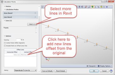
Additional functionality The dialog also provides the ability to select additional lines from Revit, and add additional lines of calculation points at specific offsets to the line previously selected. This is especially handy for exterior spill light calculations beyond the property line, or in any application where it would be beneficial to have multiple lines of adjacent points. To reveal this functionality, open the Line-Based section of the dialog. Here you can do the following:
1. Select additional lines. Open the Lines sub-section, click the Select +/- button and select the additional lines in Revit. They will be listed in the dialog. 2. Open the Options section, click in the space titled "Add a new offset line". Enter the Horizontal and Vertical Offset distances from the original line. You can do this repeatedly. |
|
|
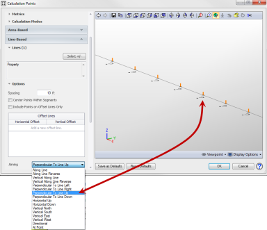
Light Meter Aiming The default light meter aiming for lines is "Perpendicular to Line Up". For a 2D line in a horizontal plane, this is identical to "Horizontal Up" which would measure horizontal illuminance (if illuminance metric is selected). However, for a 3D line, this would be "Normal" to the line. There are a diverse number of meter aiming selections available from the drop-down menu as shown at right. If you zoom into a portion of the line in the dialog viewer as shown here, you can see the light meter aiming direction for each choice.
This is very useful for different lighting applications. For example, it is common to measure vertical illuminance outside of a site property line with the light meter facing back towards the illuminated property. This would typically be "Perpendicular to Line Left" (or Right) depending on the direction of the line. Examine the meter aiming as shown in the dialog to ensure you have the proper direction. |
|
|
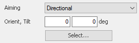
Another commonly used application is to aim all the meters in a specific direction that is not horizontal or vertical, but may follow a path of a moving camera. In this case the "Directional" option is required. When selected an additional input section will open allowing the light meter aiming angles for all points on the line to be specified. A "Select" button is also provided to allow you to return to the Revit environment to select an alignment for the Orient number graphically. You will need to enter the meter tilt manually. |
|
|
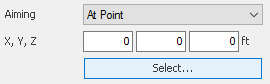
It is also common to aim all light meters at a common point such as a stationary camera. This measurement would require the light meter be aimed at a specific point, the camera location. The "At a Point" option is designed for this case. When selected, additional input cells as shown will be exposed to enter that point. A "Select" button is also provided to allow you to return to the Revit environment to select that point graphically. You may need to enter the Z-coordinate manually. |
|