
Appendix A - Calculation Methodology
ElumTools utilizes the Helios32™ radiosity engine to perform its photometric calculations and generate the interactive 3D visualizations. This is the same proven technology employed by Lighting Analysts’ standalone AGi32™ software product for lighting design and analysis (which has been in use since 1999 and validated against CIE 171:2006, Test Cases to Assess the Accuracy of Lighting Computer Programs).
Describing how the radiosity engine works in detail would require an entire book. We recommend “Radiosity: A Programmer’s Perspective” (Ashdown 1994), which is a 500-page e-book freely available here.
More simply however, we can describe the radiosity method by imagining an empty and darkened room. It has a luminaire mounted on the ceiling and a table sitting on the floor underneath it. There are no windows, open doors, or any other source of illumination.
Each surface is assigned different material properties, in this case just color/reflectance. The surfaces are divided into arrays of surface elements.
Room surface material colors
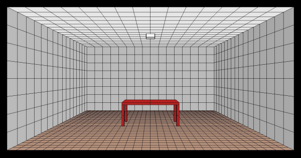
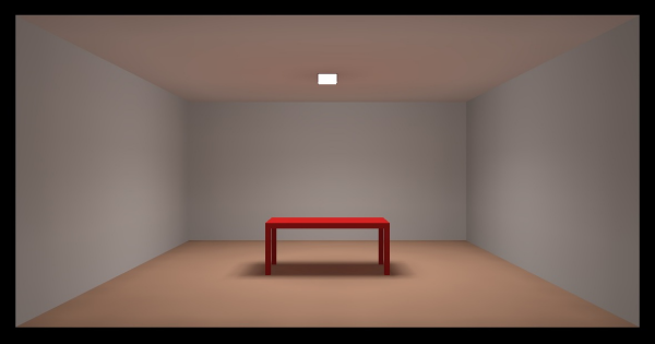
Now, turn on the luminaire. The emitted light directly illuminates the wall, floor, and table top. The sides of the table are in shadow, and the ceiling is not directly illuminated. Without any indirect illumination, the ceiling is completely black.
Direct illumination only
Depending on the surface colors, some of the light will be reflected from the directly illuminated surfaces, while the remainder will be absorbed. The reflected light will “bounce” from surface to surface in the room until it is completely absorbed. In the process, it indirectly illuminates the entire room, including the table sides and ceiling.
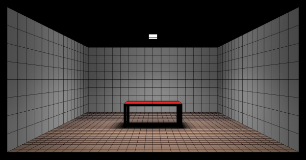
In this particular room, 50 percent of the reflected light is absorbed after 10 bounces, or radiosity steps. The convergence of the radiosity calculations begins at 0% (no indirect light absorbed) and continues until the user chooses to stop the calculations (typically at 90% to 99% convergence). The higher the convergence, the more indirect light has been taken into consideration and so the greater the accuracy of the photometric calculations.
Convergence is 50% after 10 radiosity steps
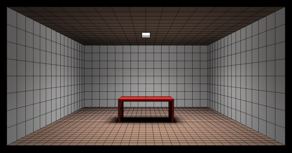
An interesting point is that the gray ceiling (actually 80% reflectance white) is distinctly brown in the above image. This is an example of “color bleeding,” where the color of one surface affects the color of an adjacent surface. This makes perfect sense when you realize that the indirect illumination of the ceiling is mostly due to reflected light from the floor. The floor is brown, and so this is the color of the reflected light. We are often not aware of this effect in real life because our “color memory” tells us that the ceiling should be white, and so we mostly ignore color bleeding.
Convergence is 90% after 200 steps
When the convergence reaches 90% (which occurs after 200 steps in this example), most of the indirect illumination on the large surfaces has been accounted for, and the radiosity calculations can be stopped if desired. Photometric measurements will be within 10% or so of the final values, which is often good enough. (For illumination engineering purposes however, 95% convergence is often preferred.)
Why continue the radiosity calculations to say 99% convergence? One reason is that each radiosity step always chooses the surface element with the most light still to be reflected. This ensures that the radiosity calculations converge as quickly as possible. However, a consequence of this iterative process is that small shadowed areas may not receive reflected light until several hundred radiosity steps have occurred.
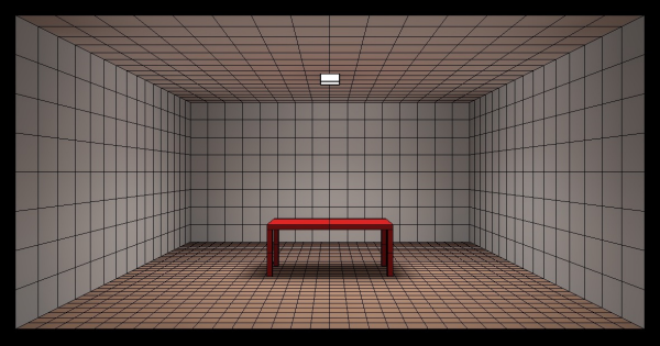
Convergence is 99% after 450 steps
Notice for example the subtle change of shadow color underneath the table that occurs between the 200th and 450th radiosity step – this is due to light being reflected multiple times between the shadowed floor and the underside of the table. Depending on the application, these details may be important.
There are of course many more details to how the radiosity calculations are performed by the Helios32 radiosity engine, many of which are explained in the e-book. There are also many more details not explained in the book, such as how the surfaces are meshed or how the photometric measurements are performed. For most applications however, it is sufficient (and useful) to have a basic understanding of how the radiosity method works.