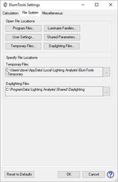

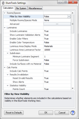
| The ElumTools Settings dialog provides access to operational elements of the software that are under user control. |
|
|
The Calculation tab provides access to all program variables that can affect the calculated and or rendered results. The default settings are appropriate for most applications.
Rooms/SpacesElumTools allows substantial flexibility in the surface geometry to be considered in a calculation. Generally speaking, the default setting is the most desirable. Additional settings can be valuable if you are interested in simplifying the geometry for speed, consistency, or flexibility in presentation.
Filter by View Visibility: It is possible to filter geometry to be included in the calculation by controlling its visibility in the 3D view titled "ElumTools_WorkingView". Use Revits' Visibility Graphics command to change entity visibility.
When 'Filter by View Visibility' is set to 'False' all elements which intersect the calculation volume (Room, Space, etc.) will be included, regardless of its visibility (in any view).
Filter by View Visibility is not applicable to the Calculate Active View or Calculate Multiple View commands. When Calculating by View, only the visibility of the calculation view will be considered. The state of the ElumTools_WorkingView is never considered when using either Calculate View command.
|
|
Multiple Rooms/Spaces Mode (default=None) This setting controls the default condition for ElumTools' calculation process when selecting multiple Rooms or Spaces for calculation. By changing this setting you can avoid the dialog that appears each time the Multiple selection is used. For a discussion on why Rooms or Spaces should be isolated or combined, please see the Calculate Rooms or Spaces topic.
None: The default setting. The Isolate or Combine choice is presented each time the Multiple command option is selected.
Isolate: This selection will bypass the dialog and always "Isolate" the multiple Room or Space selection.
Combine: This selection will bypass the dialog and always "Combine" the multiple Room or Space selection.
Advanced: The Advanced section provides very specific control settings for geometry discovery. Please see the separate topic titled Advanced Geometry Settings.
Include Luminaires (default=True): A False setting for this property will disable all luminaires in any calculation. The only reason you may want to do this is to use the various display modes in the calculation viewer to see the geometry and ensure it is what you are expecting.
Show Luminaire Validation Alerts (default=True): ElumTools will show an alert when invalid luminaires are detected in a Room or Space selected for calculation.
Enable Color Filters (default=True): A Color Filter can be applied to any light source in Luminaire Manager. Color filters behave like a "gel" in theatrical lighting and will depreciate the lumen output of the luminaire based on the filter color (Spectral Radiant Emittance).
Enable Color Temperature (default=False): Most luminaire families include a correlated color temperature value (CCT in degrees Kelvin) for the light source. By default this value is ignored and all rendering is performed with light sources using a 6500k white point. ElumTools can render color temperature convincingly. The first step is to enable Color Temperature here in Settings. The second is to set the source color in Luminaire Manager (Light Source tab - Luminous Area & Color). The Calculation viewer offers the flexibility to change the white point of the rendered display in Display Options.
Luminous Area Display Mode (default=Materials): ElumTools will display a bright luminous area by default for luminaires in the rendered view based on the setting applied here. ElumTools makes it easy to make any material appear as the luminous surface of the luminaire by using the "Luminaire Luminous" setting in Materials mapping. These settings can also be applied on the Type level from Luminaire Manager, Light Source tab.
None: disables the luminous area, all sources will appear with their standard material colors.
Emit Shape: the luminous area will correspond to the shape designated in the family light source definition.
Luminous Shape: the luminous area will correspond to the luminous area as extracted from the IES photometric file and possibly modified in Luminaire Manager.
Materials: the Materials setting will allow you to select materials used in the luminaire family housing and designate them as "luminous". This can be done in ElumTools Material Mapping by enabling the Luminaire Luminous checkbox.
If the Materials setting is applied and the luminaire has no luminous materials, one of the other modes will be used automatically. If the Revit “Emit Shape Visible in Rendering” parameter is enabled, the Emit Shape is used. Otherwise the Luminous Shape is used.
Changing the Luminous Area Display Mode does not affect the direct light emitted from the luminaire (photometric distribution). However, the luminous surfaces of a luminaire occlude (absorb), but do not reflect or transmit light. Therefore changing the size and/or location of a luminaire’s luminous surfaces may slightly affect the calculated results (due to interreflections). Note: Changing the size of the luminous shape will affect both the direct and interreflected components of the calculation.
Luminaire Area Luminance Factor (default = 10000): Determines how brightly the luminous areas of luminaires appear in the rendering. Higher values increase relative brightness. This setting has little to no effect on calculated results.
Subdivision: ElumTools subdivides area sources automatically based on their proximity to surface geometry. It may elect to not subdivide all area sources, but only those close enough to require treatment.
Minimum Luminaire Segment: The minimum subdivided segment size (in feet regardless) can be set with the "Minimum Luminaire Segment" parameter.
Force Subdivision: It is possible to force ElumTools to subdivide all area sources by enabling "Force Subdivision".
Include Surfaces with no Material: Applies a default (50% gray) material to luminaire surfaces which have no material applied. Otherwise, surfaces without a material are excluded from the calculation. Enabling this setting may cause undesired surfaces to be included in the calculation
Include Calc Points (default=True): If False, calculation points are not included in the calculations.
Results Invalidation: ElumTools invalidation routines will reset the calculation results (point-by-point results) under the following rules:
ElumTools invalidation routines are unable to detect:
Reset Invalid Results (default=True): This enables or disables the above invalidation conditions.
Show Alerts (default=True): This sets the invalidation alerts. When enabled, an alert dialog will appear whenever Revit content that has been changed will invalidate the results of a calculation per the above rules. Alerts will allow the results to be invalidated or the invalidation conditions to be ignored.
Statistics Visibility: ElumTools displays statistics from your illuminance calculations in the properties of the respective view. Ratios are employed differently internationally and ElumTools allows you to choose how you wish that information to appear.
Points Count (default=True): Displays number of calculation points in the grid.
Average (default=True): Displays the numerical average of all point values.
Minimum (default=True): Displays the minimum calculated value in the grid.
Maximum (default=True): Displays the maximum calculated value in the grid.
Avg/Min Ratio (default=True): Displays the average value divided by the minimum value as a ratio for all points in the grid.
Max/Min Ratio (default=True): Displays the maximum value divided by the minimum value as a ratio for all points in the grid.
Max/Avg Ratio (default=False): Displays the maximum value divided by the average value as a ratio for all points in the grid.
Min/Avg Ratio (default=False): Displays the minimum value divided by the average value as a ratio for all points in the grid.
Min/Max Ratio (default=False): Displays the minimum value divided by the maximum value as a ratio for all points in the grid.
Avg/Max Ratio (default=False): Displays the average value divided by the maximum value as a ratio for all points in the grid.
Points in Range (default=False): Displays the number of calculation points statistically falling within the selected range of values.
Coefficient of Variation (default=False): Displays the Coefficient of Variation for the grid.
Maximum Uniformity Gradient (default=False): Displays the Maximum Uniformity Gradient for the grid.
Save Renderings (default=Always): ElumTools default operation is to Always save your renderings in the Revit project file. You have the ability to delete them from Rendering Manager.
Light Absorbed: Please see Appendix A for an explanation of the radiosity calculation process.The most accurate radiosity calculations will be when 99% of the light originally emitted has been accounted for (absorbed). It is possible to decrease runtime by lowering the accuracy of the radiosity process by not accounting for some percentage of light still bouncing around the environment. As an example, in a complex model, often much of he final radiosity process (90% onward) can be consumed by light bouncing around in small details. This is why the maximum accuracy is set at 99%, the time for the final 1% to complete is unnecessary in terms of lighting accuracy.
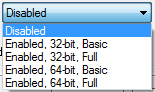
Accuracy (default=High): This sets the Stopping Criterion to preset levels of light absorbed. High=99%, Medium=95%, Low=90%. Custom allows the Stopping Criteria to be set independently. Direct Only will consider only Direct light with no interreflectance.
Stopping Criterion (default=99% corresponding to High level of Accuracy): Set this number manually when the Accuracy is set to Custom.
Interior Adaptive Subdivision:Adaptive Subdivision changes the sampling level of all surfaces based on the electric lighting
Status (default=Standard): This controls the settings below. Interior subdivision can also be disabled here.
Maximum Subdivision Level (default=3): This is the number of times ElumTools will subdivide the same element before stopping the process.
Minimum Element Area (default=.5 square feet or 0.0465 square meters): The process will stop when an elements area becomes smaller than the set value.
Element Luminance Threshold (default=1.5): This setting determines the maximum allowable difference in calculated luminous exitance between adjacent elements.
Exterior Adaptive Subdivision : Settings behave the same as Interior Adaptive Subdivision, please see the previous topic.
Secondary Sources: Secondary light sources reduce the occurrence of surface mottling which can occur due to light emitted from very bright patches incident on small elements. When secondary sources are enabled, the first bounce of light from a bright patch will be ray traced to the small elements instead of being calculated by radiosity algorithms. Ray tracing secondary sources can increase calculation times significantly but will result in smoother surfaces.
Enabled (default=false): Enable secondary source ray tracing by setting this value to True.
Threshold (default=0.01): The percentage of the total luminous flux in the environment to be emitted by any one patch. The default threshold value is 0.01 (or 1%). If the threshold value if too high (e.g. 0.1), none of the patches will be enabled as secondary sources. If the threshold value is set too low (e.g. 0.0001), too many patches will be considered as secondary sources which would have an adverse effect on calculation time. As a general rule of thumb, the threshold value should never be increased, it may be necessary to decrease the threshold value to achieve optimum results.
Meshing: The "Mesh" refers to the radiosity mesh described in Appendix A which is composed of Elements (receivers) and Patches (emitters). The density of the mesh is intelligently controlled by ElumTools to balance accuracy with run time. Meshing can be refined globally (all surfaces in the calculation) with the following settings, or can be controlled by material from within the ElumTools Materials Mapping.
Coplanar Merging (default=true): Most three dimensional objects are not optimized for radiosity calculations and rendering. For example: A round surface is typically constructed of several long and skinny triangles which commonly lead to radiosity rendering artifacts. To alleviate these artifacts, ElumTools examines each surface during the meshing process to determine if the surface is constructed of multiple polygons and, if so, merges adjacent polygons into a single polygon. This reduction in polygons has a direct effect on calculation time and reduces rendering artifacts. It is possible that extremely complex surfaces may not be handled correctly in which case coplanar merging can be disabled temporarily.
Patch Level Modifier (default=0): The number of patches (emitters) on all surfaces can be increased or decreased from this setting. Patch level can have an effect on accuracy of calculated values when set too low in complex situations. As a rule of thumb increase the patch level slightly when luminaires are very close to surfaces or when surfaces are obstructed by objects in close proximity. It is never necessary to decrease patch level.
Element Level modifier (default=0): The number of elements (receivers) can be increased or decreased with this setting. The number of elements are automatically increased when patch level is increased. The element mesh is also refined using Adaptive Subdivision therefore it is seldom necessary to increase the element level manually.
Daylight Transition Patch Level modifier (default=0): The number of patches (emitters) on all daylight transition surfaces can be increased or decreased from this setting. Think of this as increasing or decreasing the density of transfer points on the transition surface. Patch level may need to be increased when exterior shading devices are very close to transition surfaces.
Luminaire Subdivision Enabled (default=true): Allows Luminaire Subdivision to be disabled. Luminaire Subdivision settings can be found under the Luminaires topic in this Settings dialog.
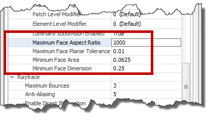
The following four parameters are designed to prohibit the software from trying to mesh surfaces that may return an error. These are typically very small or thin surfaces. These settings are best left alone unless instructed by Lighting Analysts.
A description of the Raytrace settings can be found in the topic: Calculation Viewer - Raytrace Settings.
Geometry Level of Detail (default=Fine): ElumTools will consider families that have been created with level of detail (Coarse, Medium, Fine) when parsing an environment for calculation. Use this setting to select the desired level of detail. ElumTools does not automatically pull the detail level from the Revit view.
Triangulation Level (default=0.5): Determines how (usually non-planar) surfaces are triangulated. Value should be >= 0 and <= 1. Use a value of -1 to ignore this setting (since this setting is new in ElumTools (Revit) 2014, use a value of -1 to revert to ElumTools (Revit) 2013 behavior). Large values increase mesh density (more triangles) and smaller values decrease the mesh density (fewer triangles).
Minimum Area (default=1E-06): Geometry surfaces with area smaller than this setting are excluded from the calculation and will not be visible in the visualization viewer.
Minimum Meshing Area (default=1): Only surfaces with a boundary area greater than or equal to the specified area will be assigned a valid patch/element level. All other surfaces will be assigned a patch/element level of 0/0 (one patch, one element). Increasing this value can speed up calculations by reducing the amount of patches and elements introduced by small surfaces and may reduce errors during the calculation process.
Maximum Meshing Ratio (default=400): Only surfaces with a ratio less than or equal to the specified ratio will be assigned a valid patch/element level. All other surfaces will be assigned a patch/element level of 0/0 (one patch, one element).
Patch Level Factor (default=0.25): The initial patch level for each surface is determined by the equation:
Patch Level = Max(Ceiling(A Log2 X2 + B), 0) , where:
A = Patch Level Factor
B = Patch Level Offset
X = the 3D “extents” of the surface – the length of the diagonal of the 3D axis-aligned bounding box containing the surface
Patch Level Offset (default=0): See equation for Patch Level Factor.
Element Level Tolerance (default=4): The initial element level for each surface is determined by the equation:
Element Level = If(X2 < Element Level Tolerance, 0, 1)
X = the 3D “extents” of the surface – the length of the diagonal of the 3D axis-aligned bounding box containing the surface
This means that small surfaces will have only one element per patch. All other surfaces will have four elements per patch.
Polygon Merging Mode (default=polyBoolean): Determines how polygons are merged. Do not change this setting unless told to do so by Lighting Analysts.
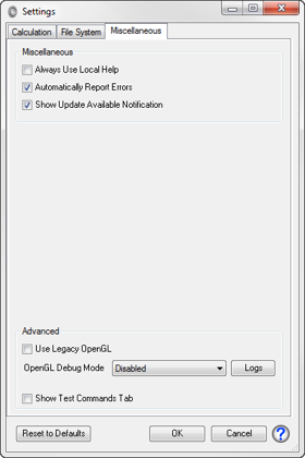
The Advanced settings are intended for troubleshooting, generally under the guidance of Lighting Analysts Customer Care technicians.
Use Legacy OpenGL: ElumTools has two OpenGL modes:
ElumTools default operations use Modern OpenGL under most graphics circumstances. If Modern OpenGL is unavailable, ElumTools will automatically fall back to the Legacy version. You can force ElumTools to utilize Legacy OpenGL for all operations by enabling the checkbox "Use Legacy OpenGL". This should only be done for computers experiencing graphics problems under normal operations. It is advisable to update your computers graphics drivers prior to enabling the legacy setting. Currently, the calculation viewer (rendered image) and the Layout Assistant always use Legacy OpenGL.
OpenGL Debug Mode: ElumTools has the ability to run a logging function in the background that can help our development team diagnose graphics issues. This should only be attempted with the supervision of our Customer Care technicians.
|
|
Reset to Defaults (button): Selecting this button will return all settings for all tabs to factory settings.
ElumTools copyright 2018 Lighting Analysts, Inc.